Bloom with Hardware Mipmap Generation
This post covers the bloom system built for a custom DirectX 12 deferred rendering engine. The engine runs an Iris-compatible shader pipeline, and the bloom implementation is part of the EnigmaDefault ShaderBundle modeled after the Complementary Reimagined visual style.
The system builds a 7-level tile atlas by sampling hardware mipmaps of the HDR scene texture with a 7x7 Gaussian kernel, then composites the result back onto the scene before tonemapping. A compute shader generates the mipmap chain one level per dispatch, using RWTexture2D UAV access to avoid SRV/UAV state conflicts. D12Texture stores per-mip UAV descriptors as persistent members, avoiding descriptor reallocations on every frame.
Rendering pipeline overview
The bloom system spans two composite passes and a compute mipmap generation step run between them. Mipmap generation runs automatically after each composite sub-pass for any render target with colortexNMipmapEnabled = true declared in the ShaderBundle.
flowchart TD
    subgraph Deferred["Deferred Pass"]
        DL["Deferred Lighting, colortex0 = HDR Scene"]
    end

    subgraph Composite["Composite Passes"]
        C1["Composite 1, Volumetric Light + Underwater"]
        MIP["Compute: Mipmap Generation, 10 Dispatch per mip chain"]
        C4["Composite 4, Bloom Tile Atlas Generation, 7x7 Gaussian x 7 LODs"]
        C5["Composite 5, Bloom Application + Tonemapping"]
    end

    DL --> C1
    C1 -->|"colortex0 written"| MIP
    MIP -->|"colortex0 mip 0-10 ready"| C4
    C4 -->|"colortex3 = tile atlas"| C5
    C5 -->|"colortex0 = LDR output"| Final["Final Pass"]
Mipmap generation system
The bloom algorithm requires downsampled versions of the HDR scene texture (colortex0) across multiple resolutions. Rather than downsampling manually inside the bloom shader, the engine computes a full mipmap chain using a compute shader. This supplies pre-filtered data at each resolution level and keeps downsampling cost off the rasterizer.
ShaderBundle configuration
Mipmap generation is opt-in per render target. The ShaderBundle marks textures that need mipmaps with a directive in the shader source, following the Iris const bool convention:
// rt_formats.hlsl
const bool colortex0MipmapEnabled = true;
The engine’s PackRenderTargetDirectives parser scans shader files during bundle load and applies the flag to RenderTargetConfig. When enabled, the render target is allocated with a full mip chain (MipLevels = floor(log2(max(width, height))) + 1). A 1920x1080 texture gets 11 mip levels.
Compute shader
Each mip level is written by a single compute dispatch using an 8x8 thread group. The shader reads the source mip through an RWTexture2D load and writes to the destination mip through an RWTexture2D store, applying a 2x2 box filter:
[numthreads(8, 8, 1)]
void main(uint3 DTid : SV_DispatchThreadID)
{
    if (DTid.x >= g_dstWidth || DTid.y >= g_dstHeight)
        return;

    RWTexture2D<float4> srcMip = ResourceDescriptorHeap[g_srcTextureIndex];
    RWTexture2D<float4> dstMip = ResourceDescriptorHeap[g_dstMipUavIndex];

    uint2 srcCoord = DTid.xy * 2;
    uint srcWidth  = g_dstWidth * 2;
    uint srcHeight = g_dstHeight * 2;

    float4 s00 = srcMip[min(srcCoord + uint2(0, 0), uint2(srcWidth - 1, srcHeight - 1))];
    float4 s10 = srcMip[min(srcCoord + uint2(1, 0), uint2(srcWidth - 1, srcHeight - 1))];
    float4 s01 = srcMip[min(srcCoord + uint2(0, 1), uint2(srcWidth - 1, srcHeight - 1))];
    float4 s11 = srcMip[min(srcCoord + uint2(1, 1), uint2(srcWidth - 1, srcHeight - 1))];

    dstMip[DTid.xy] = (s00 + s10 + s01 + s11) * 0.25;
}
Both source and destination are accessed through UAVs (RWTexture2D) instead of mixing SRV reads with UAV writes. In DX12, transitioning an entire resource into UNORDERED_ACCESS state means SRV reads (Texture2D.SampleLevel) fail because the texture is no longer in PIXEL_SHADER_RESOURCE state. Subresource barriers do not resolve this because the SRV descriptor covers all mip levels; keeping even one mip in UAV state invalidates full-resource SRV reads. Using RWTexture2D for both inputs and outputs sidesteps the issue by keeping the resource in UAV state throughout downsampling.
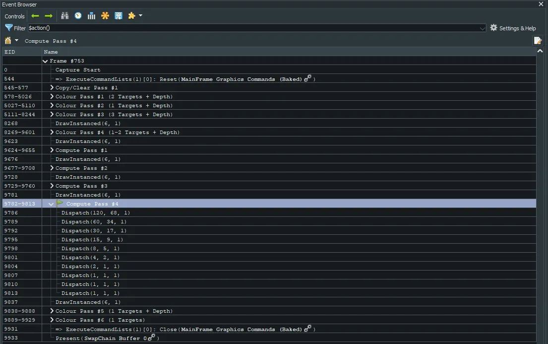
D3D12RenderSystem::CreateUAV
The engine provides a static factory for UAV creation that handles bindless index allocation and descriptor heap writes in one call:
static uint32_t CreateUAV(
    ID3D12Resource* resource,
    const D3D12_UNORDERED_ACCESS_VIEW_DESC& desc
);
The caller constructs the D3D12_UNORDERED_ACCESS_VIEW_DESC (specifying format, dimension, and mip slice) and receives a bindless index. This keeps D3D12RenderSystem general while allowing individual resource classes to configure their own descriptors, mirroring the existing TransitionResource and UAVBarrier helpers.
Persistent UAV indices on D12Texture
Per-mip UAV descriptors are stored directly on D12Texture rather than allocated per frame in MipmapGenerator.
The original implementation allocated temporary UAV indices for each dispatch and freed them after the loop. That broke because CreateUnorderedAccessView writes immediately to the GPU descriptor heap on the CPU timeline, while the GPU reads descriptors later during command list execution. Freeing and reusing an index within the same frame overwrote the descriptor before the GPU could read it.
To fix this, D12Texture creates per-mip UAV descriptors lazily on the first GenerateMips() call and keeps them until destruction. MipmapGenerator queries texture->GetMipUavIndex(mip) directly without allocating memory or descriptor slots per frame.
flowchart LR
    subgraph D12Texture["D12Texture"]
        MUI["m_mipUavIndices: [0] [1] [2] ... [10]"]
        GM["GenerateMips()"]
        CMUD["createMipUavDescriptors(), Lazy init, called once"]
        FREE["~D12Texture(), freeMipUavDescriptors()"]
    end

    subgraph MipmapGenerator["MipmapGenerator (stateless)"]
        LOOP["Per-mip dispatch loop"]
        GET["texture->GetMipUavIndex(mip)"]
    end

    GM -->|"first call"| CMUD
    CMUD -->|"D3D12RenderSystem::CreateUAV()"| MUI
    GM --> LOOP
    LOOP --> GET
    GET --> MUI
Bloom algorithm
The bloom pass builds a 7-level tile atlas based on Complementary Reimagined. Instead of using a ping-pong downsampling and upsampling chain, all 7 LOD levels are written into a single atlas in colortex3 (RGBA8).
Tile atlas layout
Each LOD level occupies a dedicated region of the atlas in normalized UV space. The layout targets 1920x1080 and rescales for other resolutions through GetBloomRescale():
+---------------------------------------+
| LOD 2 (1/4 res)                       |
| offset: (0.0, 0.0)                    |
+-------------------+-------------------+
| LOD 3 (1/8)       | LOD 4 (1/16)      |
| (0.0, 0.26)       | (0.135, 0.26)     |
+----------+--------+--------+----------+
| LOD 5    | LOD 6  | LOD 7  | LOD 8    |
| (1/32)   | (1/64) | (1/128)| (1/256)  |
+----------+--------+--------+----------+
Gaussian blur with hardware mipmaps
The BloomTile() function samples colortex0 at the corresponding hardware mip level using a 7x7 Gaussian kernel (Pascal’s triangle row 6, weights: 1, 6, 15, 20, 15, 6, 1). The hardware mipmap provides downsampling, and the Gaussian kernel applies spatial blur on top:
float3 BloomTile(float lod, float2 offset, float2 scaledCoord)
{
    float scale = exp2(lod);
    // ... tile boundary check ...

    for (int i = -3; i <= 3; i++)
        for (int j = -3; j <= 3; j++)
        {
            float  wg         = bloomWeight[i + 3] * bloomWeight[j + 3];
            float2 bloomCoord = (scaledCoord - offset + float2(i,j) * pixelSize) * scale;
            bloom += colortex0.SampleLevel(sampler0, bloomCoord, lod).rgb * wg;
        }
    bloom /= 4096.0; // 64 * 64

    return pow(max(bloom / 128.0, 0.0), 0.25); // Gamma encode
}
At mip level lod, each texel spans exp2(lod) original pixels. Kernel offsets of one screen pixel scaled by scale equal exactly one mip texel, producing a 7-texel blur at each resolution.
Gamma encoding for HDR in RGBA8
The bloom atlas (colortex3) uses an RGBA8 format to reduce memory bandwidth. To store HDR scene data in 8-bit channels, a simple gamma curve compresses and restores the dynamic range:
| Stage | Formula | Purpose |
|---|---|---|
| Encode (composite4) | pow(x / 128.0, 0.25) | Compress HDR to [0,1] for RGBA8 |
| Decode (composite5) | x^4 * 128.0 | Restore original HDR range |
The 4th-root curve distributes more precision to darker values where quantization is visible, and dividing by 128 normalizes typical HDR highlights.
Bloom pass pipeline
Composite 4: Bloom generation
This pass samples the HDR scene from colortex0 with hardware mipmaps and packs the 7-LOD tile atlas into colortex3. Higher LOD levels use lower blend weights to prevent excessive blurring at large radii:
blur += BloomTile(2.0, float2(0.0, 0.0),       scaledCoord);        // 1.0x
blur += BloomTile(3.0, float2(0.0, 0.26),       scaledCoord);        // 1.0x
blur += BloomTile(4.0, float2(0.135, 0.26),     scaledCoord);        // 1.0x
blur += BloomTile(5.0, float2(0.2075, 0.26),    scaledCoord) * 0.8;  // reduced
blur += BloomTile(6.0, float2(0.135, 0.3325),   scaledCoord) * 0.8;
blur += BloomTile(7.0, float2(0.160625, 0.3325), scaledCoord) * 0.6;
blur += BloomTile(8.0, float2(0.1784375,0.3325), scaledCoord) * 0.4;
Composite 5: Bloom application and tonemapping
This pass reads both the HDR scene (colortex0) and the bloom atlas (colortex3), combines them before tonemapping, and outputs the final LDR result:
- Read the HDR scene color
- Average all 7 LOD tiles (
* 0.14) inDoBloom()and blend withlerp(color, blur, bloomStrength) - Apply Lottes 2016 tonemapping from HDR to LDR
- Adjust color saturation and vibrance
- Output LDR color to
colortex0
Bloom strength includes a darkness adjustment (+ 0.2 * darknessFactor) that increases glow intensity in dark scenes, matching human contrast sensitivity in low light.
Bloom configuration
Bloom settings are declared in settings.hlsl as compile-time defines with slider ranges matching the Iris/OptiFine format:
| Parameter | Default | Range | Purpose |
|---|---|---|---|
BLOOM_ENABLED | 1 | -1, 1 | Enable or disable bloom entirely |
BLOOM_STRENGTH | 0.52 | 0.027 to 10.00 | Bloom intensity (lerp factor) |
The colortex0MipmapEnabled directive in rt_formats.hlsl controls whether the engine allocates hardware mipmaps for the scene texture. If disabled, sampling falls back to mip 0.
Results
Design decisions
Texture resource ownership
Per-mip UAV descriptors live directly on D12Texture as persistent members, created lazily on first use and freed in the destructor. MipmapGenerator remains a stateless utility with no per-frame allocation. This matches the ownership model used for SRV bindless indices on D12Resource.
Generic engine interfaces
D3D12RenderSystem::CreateUAV accepts a raw D3D12_UNORDERED_ACCESS_VIEW_DESC without hardcoding texture dimensions or mip slices, and D3D12RenderSystem::UAVBarrier exposes the underlying synchronization primitive. Each resource type constructs its own descriptor and passes it to the common API, keeping texture-specific details out of the core render system.
ShaderBundle-driven configuration
Mipmap generation is enabled per render target through the const bool colortexNMipmapEnabled directive in the shader source. The engine parses this during bundle loading and configures the target accordingly, allowing shader packs to request mipmaps without C++ changes.
Compute shader downsampling
The engine uses a dedicated compute shader rather than GenerateMips or CPU-side filtering. Using SM6.6 bindless RWTexture2D access avoids the resource state conflicts that occur when mixing SRV reads and UAV writes in DX12, while a 2x2 box filter produces identical results to hardware bilinear downsampling for power-of-two textures.
Looking For More?
Check out some of our other blogs if you haven't already!